Sunday, 28 July 2013

Rebuilding a 1960 Velocette Viper Clubman

Woodwork is having a summer recess while I engage in an older passion, Velocettes. I had a 1956 Venom for many years and foolishly sold it about 15 years ago, which I have always regretted. This is not a late, mid-life crisis (I had that years ago) but the engineering of Velo has always appealed to me and I think the 350cc Viper in Clubman form is a very nice example of the marque.

As only 5000 were ever built and they went bust in 1970, there are not too many around and ebay has helped hike already inflated prices. Eventually I secured one in bits on ebay which was an abandoned project. Actually that suits me as reliability of old British bikes is often reckoned to be the inverse of the number of re-builds and I need to completely strip it to be sure it is all OK.

LEP 722 was last on the road in 1976 and has since been in a lounge (with cream carpet)  in Coventry. If he ever had a wife she was surely long gone!

This is what she looked like then.


Velo's still hold the record for 100mph for 24 hours from a 500cc bike and the 350 almost emulated that achievement some years later. Unlike many modern bikes they have a very low C of G which makes them handle very nicely and as a "quality" example of British motor engineering (when we were good at such things) it is hard to beat. I remember when I was at school you could buy a Thruxton 500 Velo for £400, now selling for £20k if you can find one!

For some inexplicable reason this perfectly serviceable bike was completely stripped down, lots of new part bought but never fitted.


She is shown here "loosely assembled" for the purposes of the pic in ebay


All chains, exhaust, rebored barrel and piston were new with all the rest present but not assembled.


It has never had a modern logbook so I'll need to speak to the DVLA


Speedo showing 40k from new.

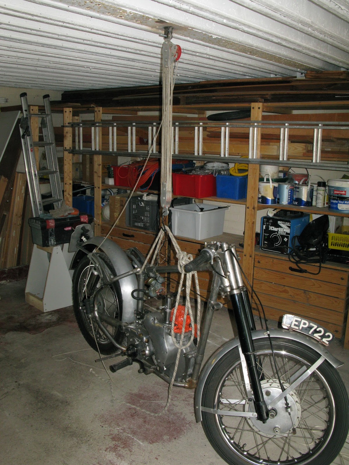
First task was getting it all home so I borrowed the works van and cleared out the garage. I needed to achieve a comfortable working height so I decided to use the stand that came with it (from the cream lounge). In order to get it there I needed a hoist so welded a couple of brackets to a convenient RSJ in the garage roof and hoped my welding had improved. I used an old Haltrac maxi-hoist last used to lift out an MGB engine gearbox and overdrive in one lump back in 1978!


Fingers crossed


Success


At least it is all clean


Beautiful bottom end and gearbox


I am now contemplating where to start to achieve a dry build to make sure everything fits and I have all the parts before stripping to send off for stove enamelling. I'll add to this thread as I go along.

Firstly I stripped off all the cycle parts to check the swinging arm and fork legs for wear. The swinging arm looked recently replaced but I fear the line reaming was poor and it was only touching in a couple of places.


I rigged up a dial gauge and found 0.10mm fore and aft on the drive side swinging arm and 0.25mm at half extension on the brake side fork leg reducing to 0.10mm at full bump position. This requires attention and I'll take a look at the bushes and measure the fork stantions for wear before going on. The swinging arm is OK for now but needs some work on the grease channels which were not correctly lined up.

It seems an odd situation re the swinging arm as it must have been renewed just before the bike was taken off the road and stripped.


Monday, 10 June 2013

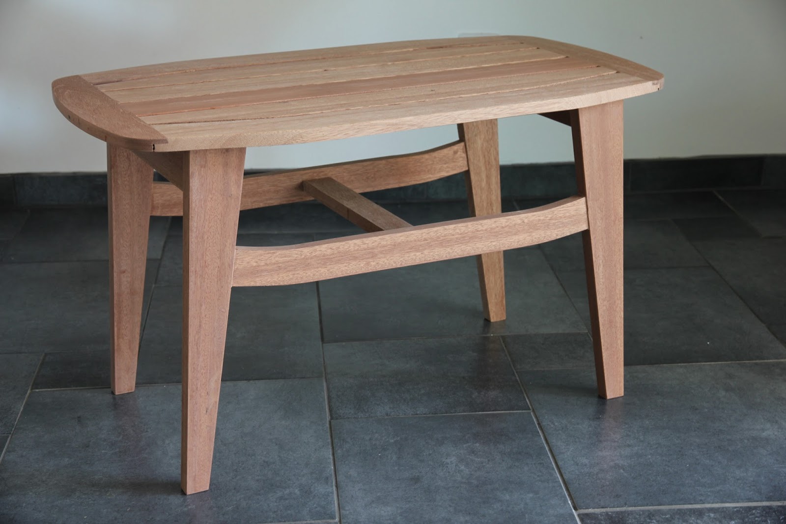
An initial deviation from the straight and narrow (or outdoor coffee table)

Much as I love planes, one problem is that they tend to produce straight square surfaces which are very inorganic and can be rather sterile in appearance. Great designs (of which this turned out not to be one), which pass test of time, tend to incorporate curves.

I had a family brief to make an outdoor table to go with a curved teak bench not more than 850mm long and be about 500mm high. That is rather high for such a small table and was to lead to problems later......

The material was entirely re-cycled Everest window boards and frames (for which there is no fate too horrible) and although the timber was technically hardwood, it had a consistency nearer to compressed cardboard. It appeared to be a low grade Sapele with the mandatory alternating grain.


The unpromising raw material


A bit of nervous nail avoidance and normal processing produced a pile of semi-decent raw material


I intended to use templates to form the curves and use the rebate block with bearings or the Felder router spindle with a template cutter. I decided to start with the top first and made up some templates from MDF for the tapered outer rails and curved ends. 

This initially required some school geometry to mark out. The multiple lines are other projects and ideas, not mistakes!!


I used the highly advanced batten and nail to mark the end radii and a bearing ring to blend the corners.


Completed template for the end. I made this full width to check the appearance although I would only use half the width at time before reversing the piece to run with the grain down both sides.


I made a double sided template to curve the outside rails, inner and outer.


And a similar template for the frame rails.


I glued up some blocks to make the curved section as I was short of wide boards and tenonned the ends on the spindle before shaping, using a false fence. I experimented with the, now superseded, Felder plastic anti-breakout block which worked well without a backing piece, just grazing the blade harmlessly. 


Tenoning the ends was done single sided on the spindle then flipped to ensure the tenon was central.  The false fence keeps everything under control and reduces the tendency to break out.


Here is a video of some of the moulding. I didn't have a suitable guard, but on template work it is possible to keep your digits a long way from the cutter, safely behind the template. 

I suppose I should say the guards were removed for photography - but they weren't.


Time to break out the spokeshaves for a clean up of the moulded edges. There have been several recent forum threads about the horrors of the spokeshave but I find if they are sharp, finely set and used skewed they are versatile and effective tools. In fact I enjoy using them and they enable many creative possibilities away from the "straight and narrow".


Excuse the exposed biscuit we can't all be perfect :-(

A dry run to see how it went together.


I tried PU foaming glue for the first time as it is supposed to be good for outside work. I don't like it as it is difficult to keep it off the surfaces as it foams and you then have a significant clean-up job afterwards. I gather you can wipe it off with acetone but I didn't have any to hand.

I spaced the slats with 8mm drills as per the drawing and it seemed to work out.


Once I'd cleaned off all the damned glue I set about chamfering the underside of the edge. I intended to use a tapered router bit in the spindle but it proved difficult to control with the weight of the top and the curves fell into the spindle aperture. I could have made up a full false fence but this was difficult with a bearing guided cutter so I marked it with a gauge and used the flat spokeshave which was quicker and easier.


I wanted to test some ideas on leg support using the minimum of cross rails and thought of a widish central spacer to prevent racking, between the side rails, which would transfer loads to all four legs whilst leaving the ends clear.

With the top made I turned my attention to the legs. I didn't see any point in thinning down the stock too much as they were 460 high and largely unsupported but this later contributed to the heaviness of the under frame appearance, so filed for future reference. The Finn Juhl method of a separate stiffener at right angles solves the problem nicely (see separate post on FJ table.)

I had made up a full size rod to prevent mistakes and transferred the angles on the ends of the legs before trimming to length on the dimension saw, using the angled fence. 

I started the long sides on the taper jig and cut out the blanks. I would normally use a crown guard with extraction but Doug had tidied it away to a place which I had not yet found :-) (I have now)


I profiled the side rails in the same way as the top and set out the joints which were dominoed but with Sapele doms to withstand the outside environment.


Owing to the curved end on the rail I had to use one side only of the narrow parts jig but this worked out fine.


Next came the end rails, dominoed to the legs. I decided to Kreg screw each slat to the rails so that they would be secure even if the glue began to fail. I also popped a Kreg into each leg.

The drill is not at an angle but I had to let go to take the picture!!


Finally a clean up before glueing up the frame. The aforementioned timber required the services of the BU smoother at high pitch to deal with the interlocked grain and I used my patent full width bench stop which is less likely to allow the component to slip off (especially with panels)


The bench stop


As is my habit, I glued up on the building board to keep everything flat and true.
More bubbling squeeze to deal with.


It took ages to clean up but the joints seem strong. I am using the top as a stressed member (much like Tim Yeo today :-))) to minimise framework, but the loads are shared between all the members and the finished table is very rigid.


I think the main problem is the heavy frame could take a larger top but that was pre-determined. I like the combination of tapered legs and curved rails but would refine the proportions next time.

I realise it is not to everyone's taste but it's a bit quirky and it's growing on me. It is finished in Sikkens Cetol Marine (a yacht varnish) for outside survival.

Thanks for looking an please post your opinions - I really am interested and pleased to receive them, good or bad.


Saturday, 1 June 2013

First ride on the new Moulton

After much wrestling with ebay I finally managed to secure a decent Moulton, with some nice gear, at a price I was prepared to pay. It is astonishing and depressing how people will pay high prices for rubbish and how many bandits there are out there. This was one of a pair, apparently owned by an old couple, and they had gradually improved them by the addition of Shimano gears, wheels, hubs and V brakes and Stronglight chainsets. It is 1994 vintage and still in the original aqua colour and generally good nick. I think I got the ladies version as it had tiny toe clips and a short stem which I will need to change.


Anyway after a bit of initial spannering to remove bells and racks and adjust the brakes, gears and suspension, it was time for a trial ride. I was very impressed by general handling and the effect of the suspension, which makes it very stable, particularly on bumpy, high speed corners and completely eliminated the bashing I normally suffer on my hands. The current tyres are a bit agricultural but over-inflated to 100 psi resulted in fine free wheeling speed. Gear changing is particularly smooth by virtue of the smaller and faster spinning wheels but is currently a bit short on the top end.

I intend to use this as a road bike and so will not make too much use of the separating facility but it is there if needed for packing in the car boot. All up weight is similar to my hybrid but it is certainly less and faster than the Brompton, which is my commuter machine.

All in all well pleased and looking forward to some fine tuning in due course.

Saturday, 11 May 2013

It may be boring to you but it is rivetting to me :-) (it's my living)

In my day job I am a bulk handling engineer and we use steel backed, wear resistant rubber to line chutes, hoppers and trucks. Fixing this is not easy and we often need to counterbore up to 120mm into the rubber at 60mm dia.

After much struggle and smoke I came across a 1930's engineering manual which suggested some cutting and clearance angles for machining rubber. I made up a boring bar with a mandrel guide to run in a pre-drilled pilot hole (which would later take the fixing)  and ground up some cutters from HSS steel lathe blanks.

The results speak for themselves, clean hole and shaving, rather than smoke and gunge.


A classic example of not re-inventing the wheel.

Friday, 10 May 2013

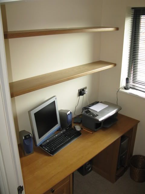
Built in torsion-box shelves

I wanted to put some shelves in an alcove of a new apartment between metal stud walls. Being new the walls were perfectly square and plumb!!! and tapered almost 10mm, inwards from back to front. This posed the first problem that if I used invisible fixing of some sort they would not slide in from the front.

The solution was to make tapered side cleats, screwed to the wall, leaving a parallel tongue to allow the shelves to slide in. 

First the torsion box shelves themselves. Foolishly I decided to use 6mm oak veneered ply which was a nightmare to keep flat and it would have been much better to use MDF.

I glued the framework which was roughly tongued together onto the first side and clamped it to the bench.


 The cross braces had a sawn tongue each end which located in a groove along the front and back rails to ensure a level.

The full depth front rail was glued to the font of the frame to allow for a radiussed edge later.


 Fitting the other face was much more difficult than I had thought owing to the wild ply and I used every cramp I had and more.


 It were a reet thrutch to get it all together but we made it in the end.


Finally a pair of very strong shelves which had no flex at all.


The front rail overhung the sides which were grooved in preparation for the cleats


The cleats were planed up with a loose tongue screwed and glued in place. The counterbores came perilously close to the edge but I just made it :-)


Test run before installation


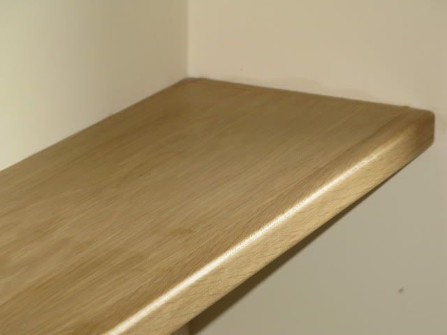
A bit of a clean up, radius the front edge and they were ready for fitting