You can never have too much tool storage and it is an opportunity to let your imagination go off a bit as only you will need to use it. I wanted access to common tools at a convenient height, in full extension drawers for easy access and had some spare kitchen cabinets left over from the utility room. I also wanted to experiment with some design ideas and construction methods prior to using them on "real" furniture.
As a fan of the late St Jim one of my experiments was going to be with organic leg proportions to see if my hypothetical formula of 25% reduction in thickness 25% of the way along the leg actually worked in practice.
I also had a small pierce of spalted beech, too small for a door panel but large enough for a decorative inlay which appealed.
Perhaps I should start with a picture of the finished cabinet so that those who are not students of JK will know what I am talking about. This is taken prior to any finish being applied and the chest is about 1200mm high

I started with the two kitchen cabinets and some redwood for the legs. I intended to template them on the spindle so needed to make up a template in MDF first. I used the 25% in 25% proportions but immediately realised this was wrong as I had not allowed for the top of the leg being smaller than the foot. This was a further 25% reduction.
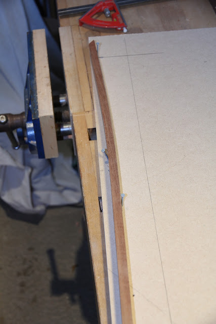
I used a batten to smooth the curve and needed a matching pair for left and right hand legs
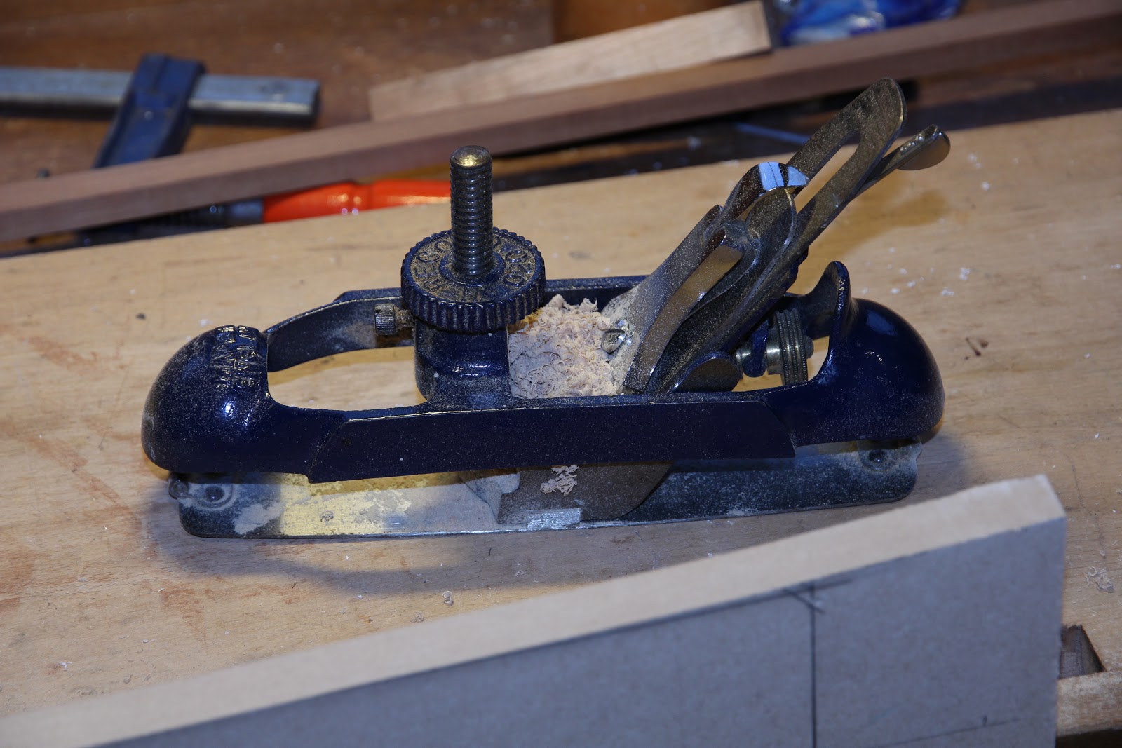
I used a circular plane to smooth the profile which worked much better than I expected, both on the template and later on the finished legs.

With some end blocks and toggle clamps attached we were ready for the shaping. Initially I bandsawed off the excess before moulding but this proved to be unnecessary and I just shaped the others directly on the spindle. It was useful have access to a tennoning hood, rather than the normal spindle fence, as this left room to manoeuvre the profile to the bearing guide.
.JPG)

I needed two cuts at different heights to complete each face.

I screwed the two cabinets together and then screwed the legs from the inside. To the horror of the purists it was very much "design as you go" in order to experiment with ideas and this applied to the angle of the legs which was achieved by trial and error before trimming the bottoms to a flat surface and the tops to what I considered at the time to be a jaunty angle to put a bit of tension to it.

I stained the legs with some left over Indian Rosewood stain but later decided to rebate them to create a step under the cabinet to take what was expected to be a considerable future load.
.JPG)
Next for the drawer carcasses. I prepared the stock from some american cherry boards I had in stock from the door casings and managed to use up all the short board ends which was satisfying as this is an expensive timber nowadays.
.JPG)
I decided to risk gang sawing for the first time and gradually worked up to four at a time which made me feel like a pieceworker.
.JPG)
I drilled a hole in the centre of the waste put and extra cut down the centre of each piece to create some clearance and ease removal after the coping saw. This works well and keeps jam ups to a minimum.
.JPG)
Ready for cleaning up
.JPG)
]
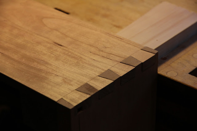
Chopping and paring back to the gauge line went well and use of the cutting gauge really helps leave a clean shoulder.
.JPG)
Having used the tails to mark the pins these were sawn out, again using a drilling to ease waste removal. This is very quick and well worth doing, especially if you have quite a few to make.

The pile slowly increased.

I tried a test fitting before going further

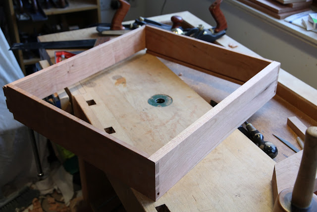
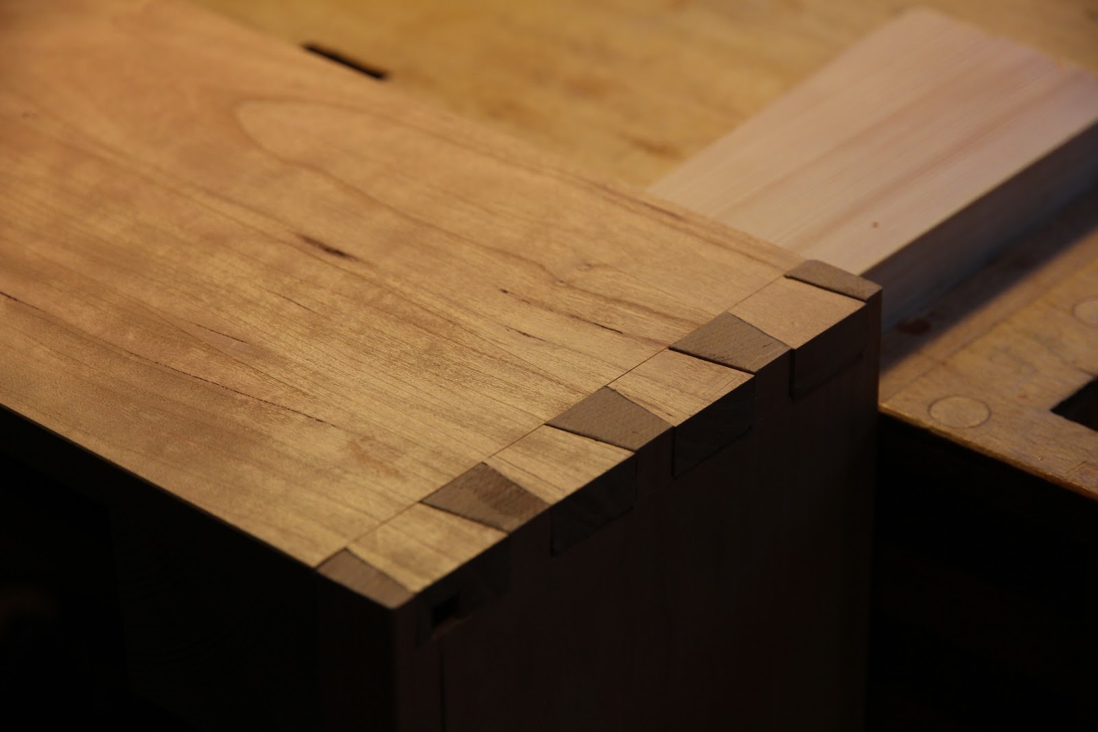
Having glued up on a building board to ensure squareness and for convenience it was time to clean up using a low angle jack on the end grain of the pins.
One down five to go. The sides were grooved directly for the 12mm veneered MDF bottoms as I was using drawer slides. I would have preferred under mounted slides but I had the side mounted ones in stock from a previous ordering mistake. As I said at the outset this cabinet was a mule for many things.
The bottoms were dimensioned on the saw, again from left overs, and fielded on the spindle to fit the 6mm grooves.

The veneered MDF was on a medite core, which I had not tried previously, and I was very pleased with the finish available directly from the machine.

The centre muntins were essential to carry the load of tools and were tennoned into the front groove and screwed up into the back with an extra long screw.

I was pleased with the way it went together and I think should stand the test of time and usage well.


Now for the all important drawer fronts which were made from the sapele treads from the old spiral staircase we had removed earlier.

Once dimensioned they were arranged for best layout although I couldn't achieve any flow over the entire front as the stairs were cut from random boards. Nevertheless it was nice timber (and free)


The fronts were spaced out to match the eventual placing and clamped up wioth wedged on the building board ready for routing out the recess for the inlay.

To prepare the inlay I edged the boards and sketched the desired profile to match the grain before folding them together and smoothing the curve with a spokeshave so that it was symmetrical.


With hindsight I may have not used the best approach to make the routing template but I decided to make a matching template to guide the router. I profiled this from MDF and carefullyt adjusted it with the spokeshave and circular plane for a dead fit on the inlay. It was easy to check by sighting agianst the light for "leaks".

I positioned the panel for best effect and placed the template

The template had to be raised on blocks to suite the only available template bit and I screwed the whole jig to the building board to prevent unwanted movement. The fronts remained clamped by wedges and screw blocks to the board although, in the event this did not prove enough to prevent movement while routing. (Another lesson learned)


I flipped the template for the other side after some careful measuring

On trial fitting all seemed well. The inlay was marked for cutting between panels.

Once trimmed each piece was glued into the appropriate drawer from and clamped securely.

Time for some more delicate smoothing with the high angle bevel up smoother

Next it was time to fit the drawers and slides. I decided to make some spacers to position the slides in the carcass. These had to be made precisely to size to maintain the spacing so were shot with the LA jack (any excuse :-))

I clamped the slides above the spacers which ensured the correct positioning on both sides.


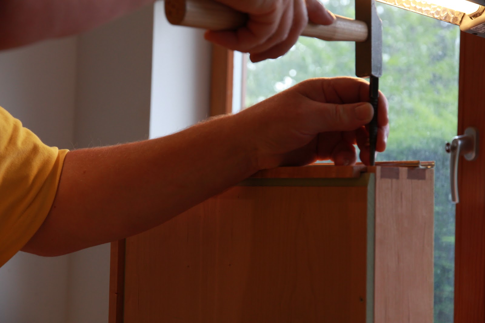
I have a tendency to go back to my engineering background when looking for accuracy and centre punched the screw positions in the drawer sides. I am not convinced this is the correct approach as the center punch has a tendency to follow the grain. (not a problem with mild steel). Note the £3 Euro hammer from the tragic Footprint liquidation.

Drawers trial fitted, ready for final adjustment, and began fitting the fronts.

Finally got it all together

Quickly filled with waiting tools

Not to everyone's taste I know but like it :-) thanks for looking

As a fan of the late St Jim one of my experiments was going to be with organic leg proportions to see if my hypothetical formula of 25% reduction in thickness 25% of the way along the leg actually worked in practice.
I also had a small pierce of spalted beech, too small for a door panel but large enough for a decorative inlay which appealed.
Perhaps I should start with a picture of the finished cabinet so that those who are not students of JK will know what I am talking about. This is taken prior to any finish being applied and the chest is about 1200mm high

I started with the two kitchen cabinets and some redwood for the legs. I intended to template them on the spindle so needed to make up a template in MDF first. I used the 25% in 25% proportions but immediately realised this was wrong as I had not allowed for the top of the leg being smaller than the foot. This was a further 25% reduction.

I used a batten to smooth the curve and needed a matching pair for left and right hand legs
I used a circular plane to smooth the profile which worked much better than I expected, both on the template and later on the finished legs.
With some end blocks and toggle clamps attached we were ready for the shaping. Initially I bandsawed off the excess before moulding but this proved to be unnecessary and I just shaped the others directly on the spindle. It was useful have access to a tennoning hood, rather than the normal spindle fence, as this left room to manoeuvre the profile to the bearing guide.
.JPG)

I needed two cuts at different heights to complete each face.

I screwed the two cabinets together and then screwed the legs from the inside. To the horror of the purists it was very much "design as you go" in order to experiment with ideas and this applied to the angle of the legs which was achieved by trial and error before trimming the bottoms to a flat surface and the tops to what I considered at the time to be a jaunty angle to put a bit of tension to it.

I stained the legs with some left over Indian Rosewood stain but later decided to rebate them to create a step under the cabinet to take what was expected to be a considerable future load.
.JPG)
Next for the drawer carcasses. I prepared the stock from some american cherry boards I had in stock from the door casings and managed to use up all the short board ends which was satisfying as this is an expensive timber nowadays.
.JPG)
.JPG)
I drilled a hole in the centre of the waste put and extra cut down the centre of each piece to create some clearance and ease removal after the coping saw. This works well and keeps jam ups to a minimum.
.JPG)
Ready for cleaning up
.JPG)
]
Chopping and paring back to the gauge line went well and use of the cutting gauge really helps leave a clean shoulder.
.JPG)
Having used the tails to mark the pins these were sawn out, again using a drilling to ease waste removal. This is very quick and well worth doing, especially if you have quite a few to make.

The pile slowly increased.

I tried a test fitting before going further

Having glued up on a building board to ensure squareness and for convenience it was time to clean up using a low angle jack on the end grain of the pins.
One down five to go. The sides were grooved directly for the 12mm veneered MDF bottoms as I was using drawer slides. I would have preferred under mounted slides but I had the side mounted ones in stock from a previous ordering mistake. As I said at the outset this cabinet was a mule for many things.

The bottoms were dimensioned on the saw, again from left overs, and fielded on the spindle to fit the 6mm grooves.

The veneered MDF was on a medite core, which I had not tried previously, and I was very pleased with the finish available directly from the machine.

The centre muntins were essential to carry the load of tools and were tennoned into the front groove and screwed up into the back with an extra long screw.

I was pleased with the way it went together and I think should stand the test of time and usage well.


Now for the all important drawer fronts which were made from the sapele treads from the old spiral staircase we had removed earlier.

Once dimensioned they were arranged for best layout although I couldn't achieve any flow over the entire front as the stairs were cut from random boards. Nevertheless it was nice timber (and free)


I book matched the board of spalted beech which had been in stock waiting for this day for many years and bandsawed it down to 4mm then 3mm on the thicknesser. I had the idea of a cascade effect down the front placed off to one side.

The fronts were spaced out to match the eventual placing and clamped up wioth wedged on the building board ready for routing out the recess for the inlay.

To prepare the inlay I edged the boards and sketched the desired profile to match the grain before folding them together and smoothing the curve with a spokeshave so that it was symmetrical.


With hindsight I may have not used the best approach to make the routing template but I decided to make a matching template to guide the router. I profiled this from MDF and carefullyt adjusted it with the spokeshave and circular plane for a dead fit on the inlay. It was easy to check by sighting agianst the light for "leaks".

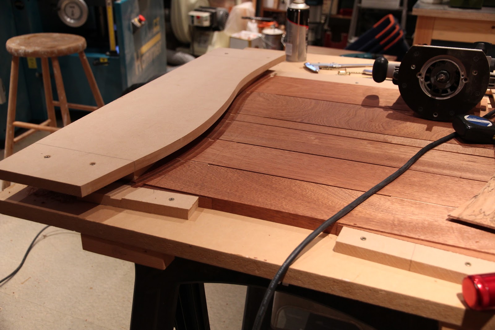
I positioned the panel for best effect and placed the template

The template had to be raised on blocks to suite the only available template bit and I screwed the whole jig to the building board to prevent unwanted movement. The fronts remained clamped by wedges and screw blocks to the board although, in the event this did not prove enough to prevent movement while routing. (Another lesson learned)

I flipped the template for the other side after some careful measuring

On trial fitting all seemed well. The inlay was marked for cutting between panels.

Once trimmed each piece was glued into the appropriate drawer from and clamped securely.

Time for some more delicate smoothing with the high angle bevel up smoother

Next it was time to fit the drawers and slides. I decided to make some spacers to position the slides in the carcass. These had to be made precisely to size to maintain the spacing so were shot with the LA jack (any excuse :-))

I clamped the slides above the spacers which ensured the correct positioning on both sides.


I have a tendency to go back to my engineering background when looking for accuracy and centre punched the screw positions in the drawer sides. I am not convinced this is the correct approach as the center punch has a tendency to follow the grain. (not a problem with mild steel). Note the £3 Euro hammer from the tragic Footprint liquidation.
Drawers trial fitted, ready for final adjustment, and began fitting the fronts.

Finally got it all together

Quickly filled with waiting tools

Not to everyone's taste I know but like it :-) thanks for looking

No comments:
Post a Comment